Connecting
The Quicktake 100 and 150 are connected via serial. Both share the same protocol.
Once connected, one has to open the lens cover to power on the camera. Unusually enough, the “conversation” is started by the camera, which is the first to send bytes to the computer. The computer signals it is ready to interact with the camera by opening the serial port at 9600bps, 8 data bits, 1 stop bit, no parity, no flow control. Opening the serial port sets DTR up, and right after that, the computer toggles DTR down. This up/down on DTR is what wakes up the QuickTake.
The flow is the following:
- Computer: opens port at 9600 8n1 (POSIX code)
- Computer: clears DTR (POSIX code)
- Camera: sends 7 bytes – I have not yet found a real use for them, but they can be used to differentiate the Quicktake 100, 100 Plus and 150. My QuickTake 100 sends the following:
- QuickTake 100: {0xA5, 0x5A, 0x01, 0x01, 0x01, 0x00, 0x02}
- Computer: replies with one of the following:
- {0x5A,0xA5,0x55,0x05,0x00,0x00,0x25,0x80,0x00,0x80,0x02,0x00,0x80} for 9600bps communication
- {0x5A,0xA5,0x55,0x05,0x00,0x00,0x4B,0x00,0x00,0x80,0x02,0x00,0x26} for 19200bps communication
- {0x5A,0xA5,0x55,0x05,0x00,0x00,0x96,0x00,0x00,0x80,0x02,0x00,0x71} for 38400bps communication
- {0x5A,0xA5,0x55,0x05,0x00,0x00,0xE1,0x00,0x00,0x80,0x02,0x00,0xBC} for 57600bps communication
- In this command, bytes 0x06 and 0x07 represent the desired speed, and the last byte (0x0C) is a checksum of the previous ones, added together and ANDed with 0x00ff.
- The desired speed is indicated there, but we are still at 9600bps for now. Toggling to a faster speed is done in the next step.
- Camera: sends 10 bytes – I have not yet found a use for them, but they probably are useful to differentiate the Quicktake 100, 100 Plus and 150. My QuickTake 100 sends the following:
- QuickTake 100: {0x00, 0x00, 0x00, 0x00, 0xE1, 0x00, 0x00, 0x80, 0x02, 0x00}
- Note: in this response, the Quicktake agrees to 57600bps.
At this point, the computer is expected to turn Even parity on.
After Even parity is set, a slight delay is needed before continuing with the next step, upgrading speed. This step is optional and not needed for 9600bps communication, but if you don’t do it, you have to send a “ping” instead (see below).
- Computer: waits about 1 second
- Computer: sends a command in which byte 0x0D differs with the target speed:
- {0x16,0x2A,0x00,0x03,0x00,0x00,0x00,0x00,0x00,0x05,0x00,0x03,0x03,0x08,0x04,0x00} for 9600 bps
- {0x16,0x2A,0x00,0x03,0x00,0x00,0x00,0x00,0x00,0x05,0x00,0x03,0x03,0x10,0x04,0x00} for 19200 bps
- {0x16,0x2A,0x00,0x03,0x00,0x00,0x00,0x00,0x00,0x05,0x00,0x03,0x03,0x20,0x04,0x00} for 38400 bps
- {0x16,0x2A,0x00,0x03,0x00,0x00,0x00,0x00,0x00,0x05,0x00,0x03,0x03,0x30,0x04,0x00} for 57600 bps
- Camera: acks with {0x00}
- Computer: acks with {0x06}
- Computer: waits 100 milliseconds
- Computer: toggles serial line speed to the desired speed
While we wait and toggle our serial speed, the camera sends 1024 bytes of data (1kB of 0xAA), which I found no use for. The timing to get all the 1024 bytes is not easy to get. Simplest thing to do is read with timeout until nothing arrives for a few hundreds milliseconds, and discard.
After that,
- Computer send an ack: {0x06}
- Camera replies with {0x00}
Pinging the camera
A simple command that does nothing except elicit a single-byte response from the camera. It is very useful to verify that the camera is still connected and turned on before sending other commands. The flow is the following:
- Computer: sends {0x16,0x00,0x00,0x00,0x00,0x00,0x00}
- Camera: responds with {0x00}
Note: when the camera responds with 0x02 instead of 0x00, in reply to any command, it means it’s unhappy with your command.
I use this function before every other function to simplify error handling.
Getting camera information
The flow for getting the camera information is the following:
- Computer: sends {0x16,0x28,0x00,0x30,0x00,0x00,0x00,0x00,0x00,0x80,0x00}
- Camera: acks with {0x00}
- Computer: responds with {0x06}
- Camera: responds with 128 bytes of data.
In the response data, starting from byte 0, are the following:
- byte 0x02: Battery level as a percentage (8-bit value)
- byte 0x04: Number of pictures taken (8-bit value)
- byte 0x06: Number of pictures left (in the current quality mode)
- byte 0x10: Current month
- byte 0x11: Current day of month
- byte 0x12: Current year (this is also an 8-bit value, so “23” for 2023)
- byte 0x13: Current hour
- byte 0x14: Current minute
- byte 0x15: Current second
- byte 0x16: Current flash mode (0: auto, 1: disabled, 2: forced)
- byte 0x1B: Current quality mode (0x20: 320×240, 0x10: 640×480)
- bytes 0x2F to 0x4F: Name of the camera, trailed with spaces to 32 characters, and NULL-terminated
(As an aside, in most commands sent by the computer, bytes 7 to 9 (counting from 0) contain the expected response size, in 24 bits, big-endian format)
Getting a picture
There are two commands to get a picture.
Getting the “header”, basic information about the picture:
It will be needed later. The flow for getting the header is the following:
- Computer: sends {0x16,0x28,0x00,0x21,0x00,0x00,0x03,0x00,0x00,0x40,0x00}. Byte 0x06 is the picture number, starting from 1 and up to the number of pictures stored in the camera (picture 3 in this example) .
- Camera: acks with {0x00}
- Computer: responds with {0x06}
- Camera: responds with 64 bytes of data.
In the response data, starting from byte 0, are the following:
- byte 0x03: the picture number
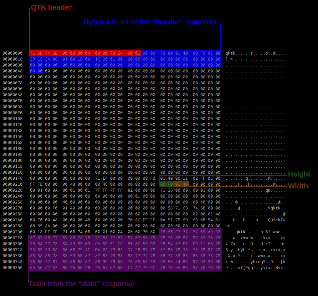
- byte 0x04-0x40: the important part of the qtkt header, notably containing:
- byte 0x05-0x07: Image size, 24-bytes, big-endian. It will either be 115200 (high quality) or 28800 (standard quality).
- byte 0x08-0x09: Image width, 16-bits, big-endian
- byte 0x0A-0x0B: Image height, 16-bits, big-endian
- Bytes 0x0D-0x12: Image timestamp, six 8-bit values representing month/day/year/hour/minute/second
- Byte 0x13: Flash (1: Flash was fired, 0: no flash)
- Byte 0x18: Quality mode (0x20: standard, 0x10: high) ? Unsure about this one
Before getting the picture, which will be raw ADPCM-compressed data for QuickTake 100 and RADC-compressed data for QuickTake 150, it might be useful to prepare the header of the output file, so that tools like dcraw can read and decode them. The qtkt (from QuickTake 100) and qtkn (from QuickTake 150) files have the following format:
- starts with:
- {0x71,0x6B,0x74,0x6B,0x00,0x00,0x00,0x04,0x00,0x00,0x73,0xE4,0x00,0x01} for standard-quality qtkt (QT100) files
- {0x71,0x6B,0x74,0x6B,0x00,0x00,0x00,0x08,0x00,0x01,0xC5,0x64,0x00,0x05} for high-quality qtkt (QT100) files
- {0x71,0x6B,0x74,0x6E,0x00,0x00,0x00,0x04,0x00,0x00,0x73,0xE4,0x00,0x01} for qtkn (QT150/200 files)
- Note: the bytes values highlighted vary. The Quicktake software set them with more care than I do in my implementation, but as they are useless to both dcraw and my Apple II software, I have not yet investigated them. Help welcome on this! I think that:
- Byte 0x07, either 4 or 8 here, is a quality indicator for QT100, and a rotation indicator for QT150.
- Bytes 0x09-0x0B are the full size of the file (files made by the real software are bigger, they contain metadata and the thumbnail at their end)
- Byte 0x0D may contain the flash mode used to take the picture
- 736 bytes long header (only the fourth byte differ, the first four bytes being “qtkt” or “qtkn”)
- byte 0x0E, the last 60 bytes of the camera’s response: the important part of the qtkt header
- bytes 0x220-0x221: height of the picture (again), 16-bit word, big-endian
- bytes 0x222-0x223: width of the picture (again), 16-bit word, big-endian
- 0x2E0-end of file: the image data
Apart from bytes 0x220-0x223, the bytes from 0x4A to 0x2DF are useless, at least to dcraw.
The easiest way to build the header is to write 736 NULL bytes to the output file, rewind, seek, and write the relevant parts. I am unsure if the resulting file is valid for the official, vintage Quicktake software, but it is valid enough for dcraw to decode it correctly.
A picture being worth a thousand words, here is a annotated hexadecimal dump of a QuickTake 100 picture. This one is 320×240 pixels.
Getting the picture data:
The next command will get the data of the photo. The flow is the following:
- Computer: sends {0x16,0x28,0x00,0x10,0x00,0x00,0x01,0x00,0x70,0x80,0x00}. Byte 0x06 is the number of the picture, and bytes 0x07-0x09 are the size of the answer we expect, as a 24-bit, big-endian number. It has to match the size of the picture that we learnt in the previous command. (Picture 1 in this example, 0x007080 bytes long)
- Camera: sends {0x00}
- Computer: sends {0x06}
- Camera: sends N bytes of data, depending on the picture’s quality (0x7080 or 0x01C200 for QuickTake 100 pictures, a varying number for QuickTake 150 pictures). The data is sent by blocks of 512 bytes, and the computer acks each block by sending {0x06}. At the end of the transfer, the last block will be shorter than 512 bytes (it will be size modulo 512 bytes), and the computer must not send a {0x06} ack at the end of it.
Getting a thumbnail:
It is possible to get a thumbnail, a 80×60 pixels version of the photo. We receive 2400 bytes of data, encoded at 4-bits per pixel and that, for the QuickTake 100, is very easy to decode:
  for (y = 0; y < 60; y++) {
    for (x = 0; x < 80; x+=2) {
      fread(&c, 1, 1, thumbnail_file);
      a = (((c>>4) & 0b00001111) << 4);
      b = (((c)    & 0b00001111) << 4);

      image[y][x] = a;
      image[y][x + 1] = b;
    }
  }
For the QuickTake 150, it’s a bit harder, and out of this document’s scope, please see the libgphoto2 implemention, or the Quicktake for Apple II implementation (less legible because of all the trying to spare cycles and memory).
The flow for getting a thumbnail is the same as getting the full picture, and the command is {0x16,0x28,0x00,0x00,0x00,0x00,0x01,0x00,0x09,0x60,0x00}. Byte 0x03 is different, and bytes 0x07-0x09 are 0x000960, which is 2400 bytes.
Deleting all photos on the camera
It is only possible to delete all pictures, but not possible to delete a single one. The flow for deleting all pictures is:
- Computer: sends {0x16,0x29,0x00,0x00,0x00,0x00,0x00,0x00,0x00,0x00,0x00}
- Camera: sends {0x00} (takes a few seconds to come)
The computer does not answer that {0x00} ack.
Setting the camera name
It is possible to change the camera’s name in the following way:
- Computer: sends {0x16,0x2a,0x00,0x02,0x00,0x00,0x00,0x00,0x00,0x22,0x00,0x02,0x20,0x43,0x6F,0x6C,0x69,0x6E,0x20,0x20,0x20,0x20,0x20,0x20,0x20,0x20,0x20,0x20,0x20,0x20,0x20,0x20,0x20,0x20,0x20,0x20,0x20,0x20,0x20,0x20,0x20,0x20,0x20,0x20,0x20}
- Camera: acks with {0x00}
The computer does not answer that ack. The new camera name is at byte 0x0D, and must be precisely 32 bytes long (padded with trailing spaces). In this example, the camera name is “Colin “.
Setting the camera time
It is possible to set the camera’s time in the following way:
- Computer: sends {0x16,0x2A,0x00,0x01,0x00,0x00,0x00,0x00,0x00,0x08,0x00,0x01,0x06,0x00,0x00,0x00,0x00,0x00,0x00}
- Camera: acks with {0x00}
The computer does not answer that ack. The date and time are encoded in one 8-bit value per field:
- byte 0x0D: month (1 to 12)
- byte 0x0E: day
- byte 0x0F: year (23 for 2023)
- byte 0x10: hour
- byte 0x11: minute
- byte 0x12: second
Taking a picture
Taking a picture is really easy:
- Computer: sends {0x16,0x1B,0x00,0x00,0x00,0x00,0x00}
- Camera: acks with {0x00} (the ack takes a few seconds to come)
The computer does not answer that ack, and the camera takes a picture. The camera does not send the picture’s number back or anything – the picture taken is simply the last one.
Setting the quality mode
- Computer: sends {0x16,0x2A,0x00,0x06,0x00,0x00,0x00,0x00,0x00,0x04,0x00,0x06,0x02,0x10,0x00}, where byte 0x0D is either:
- 0x10 for high quality mode
- 0x20 for standard quality mode
- Camera: acks with {0x00}
Setting the flash mode
- Computer: sends {0x16,0x2A,0x00,0x07,0x00,0x00,0x00,0x00,0x00,0x03,0x00,0x07,0x01,0x00}, where byte 0x0D is either:
- 0x00 for Automatic flash
- 0x01 for Flash off
- 0x02 for Flash forced on
- Camera: acks with {0x00}
Setting timer mode
The last control available in the old QuickTake software is to set the timer mode, either enabled or disabled. However, toggling this control is internal to the software, does not get set in the camera, and I suspect the software just adds a sleep() before taking the picture.
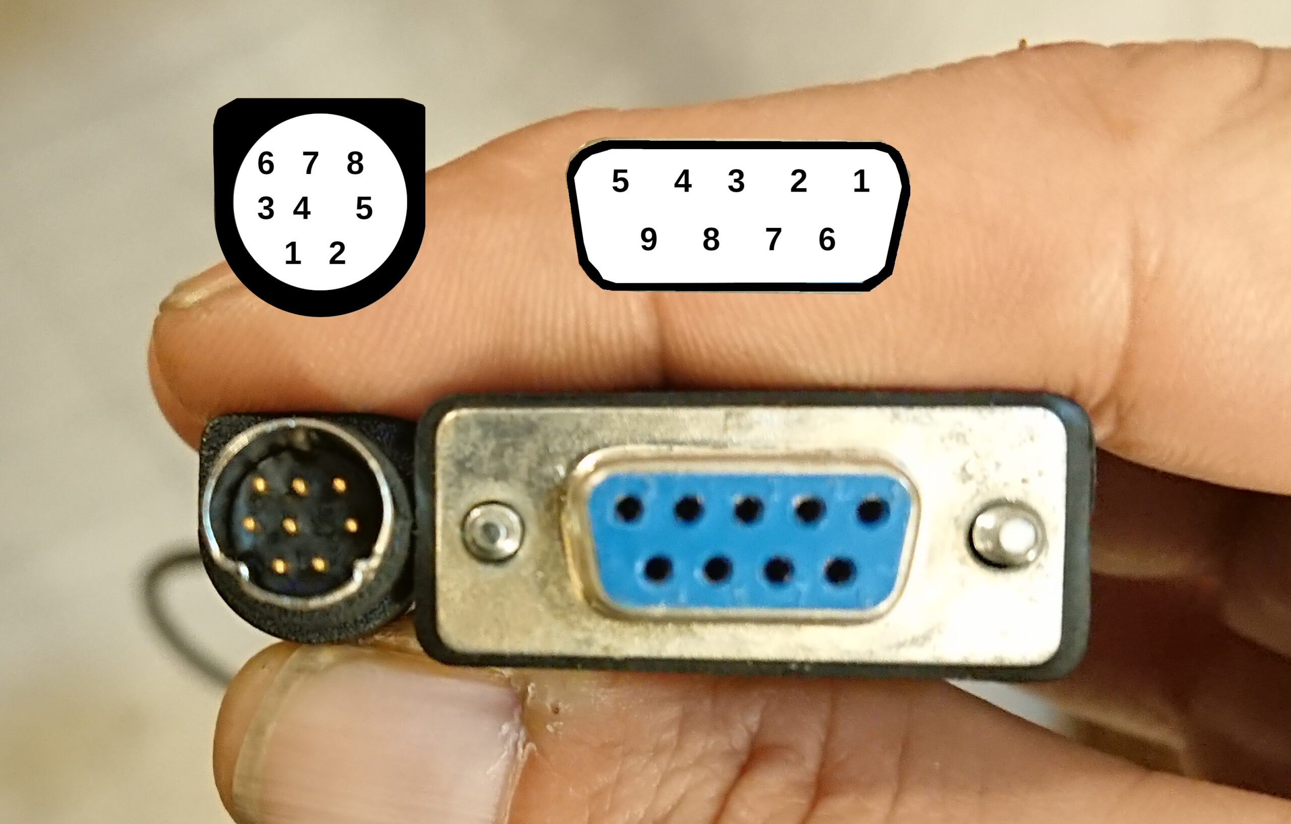
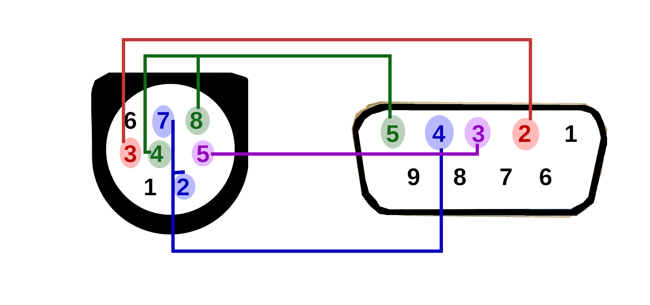
The cable
For reference, here is the wiring of the mini-DIN-8 to DB-9 cable provided by Apple in the “for Windows” Quicktake box.
Known implementations
This protocol is now implemented in three different projects:
- Quicktake for Apple II, of course (by myself)
- Gphoto2 (not yet released, but available in git; by myself)
- JQuicktake (by Kevin Godin)
Final words
There may be errors or omissions in this document. It has been derived from my implementation of the Quicktake 100 serial protocol, so in case of doubts, please check the source code. I will gladly correct and complete this document as needed.

Thank you very very much for you article. I have soldered a cable for brothers camera according to your pinout picture (it was old Olympus that he know uses the same cable).
This article is a jam! I’m making a python module that can send data to an ImageWriter and I really like this feeling of making obsolete thing come to life. I’m searching for a QuickTake to use it to make it work based on this article.