A little technical post to document something that was apparently not obvious to everybody. I want to make it clear that this article is not a discovery. It’s an explanation on the “how”.
I recently questioned myself and others in the Apple II dev community about the Apple II MouseCard, its interrupts, and their synchronisation with the Apple II vertical blanking.
Documentation about the card states that the IRQ is synchronised to the VBL:
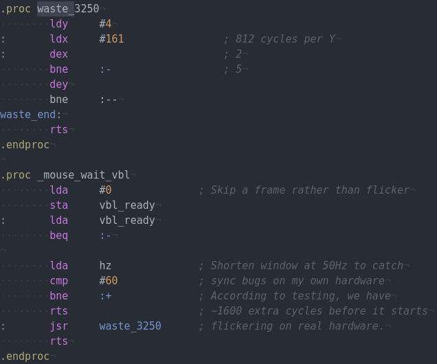
I wondered a lot about this, stemming from the fact that under MAME emulation, my Shufflepuck game flickered a lot, whereas in real life, it was very cleanly rendered. Of course in my real life, I can test it on an Apple //c, which doesn’t exactly have a MouseCard but a compatible mouse firmware, and also it’s a PAL Apple, so it’s running at 50Hz and not 60. When I want to test if my drawing is fast enough for 60Hz Apple II, I have to waste 3250 cycles before starting to draw.
So I could not do the exact tests I wanted, and I had to ask nice people to test on their NTSC Apple IIe, multiple times, to make sure I was doing things as they should be done. All of the people who tried told me it was fine and not flickering, some with videos (thanks, folks!)… but a few people that are otherwise very knowledgeable told me that the mouse IRQ was not, and/or could not, be synced to the VBL, because the mouse card had no way to know about the VBL. That, at best, it could be “synchronised” as in “firing at the same frequency”.
I ended up opening an issue on MAME’s tracker, complete with schematics of my questions about this mystery:
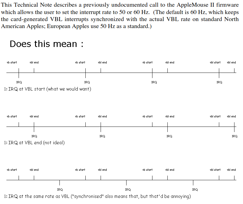
While the bug in MAME is not yet fixed, the investigations into it by Robert Justice and R. Belmont (and a bit of myself) made one thing very clear:
Yes, the Apple II MouseCard IRQ is precisely synchronised to the VBL signal, and fires at the same time as the VBL signal.
First of all, when the programmer calls MOUSE_INIT, the mouse firmware waits for vertical blanking. On the Apple IIe, it does so by watching RDVBL at $C019; on the Apple ][+, where this softswitch is not available, it does so by setting up an HGR page full of zeroes and a few different bytes at the relevant places, and then performs a vapor lock. It may be less precise by a couple of cycles, but it is good enough to determine where the beam is on the screen.
Here is an extract of the AppleMouse firmware code waiting for VBL on a IIe:
; Here we are in my code, preparing to call MOUSE_INIT.

A=00 X=C4 Y=40; N....IZ.; 6E90: ldx #$19      ; Load MOUSE_INIT entry point ID
A=00 X=19 Y=40; .....I..; 6E92: jsr $6eaf     ; Jump to firmware calling subroutine
A=00 X=19 Y=40; .....I..; 6EAF: ldy $c400, x  ; Get the firmware jump target low byte
A=00 X=19 Y=BC; N....I..; 6EB2: sty $6eba     ; Patch our code to jump
A=00 X=19 Y=BC; N....I..; 6EB5: ldx #$c4      ; Load X and Y according to the
A=00 X=C4 Y=BC; N....I..; 6EB7: ldy #$40      ; mousecard specifications
A=00 X=C4 Y=40; .....I..; 6EB9: jmp $c4bc     ; Jump to mouse firmware INIT

; Now we enter the mouse firmware, and watch it wait for VBL start.
[...]
A=06 X=C4 Y=40; .....IZC; C426: lda RDVBL     ; The mouse firmware waits for start
A=80 X=C4 Y=40; N....I.C; C429: bmi $c426     ; of vertical blanking
[...]
A=00 X=C4 Y=40; .....IZC; C42B: lda RDVBL     ; Now it waits for start of beam drawing
A=80 X=C4 Y=40; N....I.C; C433: bpl $c430     ; on the screen
[...]
A=80 X=C4 Y=40; N....I.C; C430: lda RDVBL     ; And wait for start of VBL again
A=00 X=C4 Y=40; .....IZC; C433: bmi $c430
[...]                                         ; At that point, VBL just started
This part explains the “how does the AppleMouse card know about VBL when it doesn’t have that signal available”: it does it like we programmers do, via software.
Now for the other question: How does the MouseCard fire its IRQ at the same rate as VBL? the framerate of the NTSC Apple II is 59.92Hz, and 50.32Hz for the PAL Apple II.
Once the MouseCard firmware has caught a VBL start, it sets up the 68705 CPU, using the 6821 PIA that it ships with.
In the following extract, I only kept the read/writes to the PIA registers:
A=00 X=C4 Y=40; .....IZC; C470: lda $c082, y  ; Read PIA 0x2
A=0C X=C4 Y=40; .....I.C; C478: sta $c082, y  ; Write 0x0C to PIA 0x2
A=00 X=C4 Y=40; .....IZC; C416: lda $c082, y  ; Read PIA 0x2
A=0C X=C4 Y=40; .....I.C; C41B: lda $c081, y  ; Read PIA 0x1
A=00 X=C4 Y=40; .....IZC; C420: sta $c081, y  ; Write 0x0C to PIA 0x1
A=FF X=C4 Y=40; N....I.C; C425: sta $c080, y  ; Write 0xFF to PIA 0x0
A=FF X=C4 Y=40; N....I.C; C428: lda $c081, y  ; Read PIA 0x1
A=04 X=C4 Y=40; .....I.C; C42D: sta $c081, y  ; Write 0x04 to PIA 0x1
A=50 X=C4 Y=40; .....I.C; C431: sta $c080, y  ; Write 0x50 to PIA 0x0
                                              ; INIT_MOUSE command

                                              ; Wait for ack of cmd
A=50 X=C4 Y=40; .....I.C; C434: lda $c082, y  ; Read PIA 0x2
A=0C X=C4 Y=40; .....I.C; C437: ora #$20      ; Set bit5
A=2C X=C4 Y=40; .....I.C; C439: sta $c082, y  ; Write 0x2C to PIA 0x2
                                              ; Sets bit1 of 6805 PORTC
A=2C X=C4 Y=40; .....I.C; C43C: lda $c082, y  ; Read PIA 0x2
A=2C X=C4 Y=40; .....I.C; C43F: bpl $c43c     ; Until high bit is set
[...]
A=2C X=C4 Y=40; .....I.C; C43C: lda $c082, y
A=AC X=C4 Y=40; N....I.C; C43F: bpl $c43c     ; It is now, ack done
A=AC X=C4 Y=40; N....I.C; C441: and #$df
A=8C X=C4 Y=40; N....I.C; C443: sta $c082, y  ; Write 0x8C to PIA 0x2
A=80 X=C4 Y=40; N....I..; C470: lda $c082, y  ; Read PIA 0x2
A=84 X=C4 Y=40; N....I..; C478: sta $c082, y  ; Write 0x84 to PIA 0x2
A=00 X=C4 Y=40; .....IZ.; C470: lda $c082, y  ; Read PIA
A=00 X=C4 Y=40; .....IZ.; C478: sta $c082, y  ; Write 0x00 to PIA 0x2
Basically during that VBL loop at C430-C433, the 68705 loops on 55E: brclr 1, PORTC, $55E. As soon as 0x2C is written to PIA’s 0x2, the 65705 exits its loop at 55E and sets TDR to $FF, clears interrupt request on TCR, and sets TDR to the value at $52:
561: lda   #$FF
563: sta   TDR
565: bclr  7, TCR
567: cli
568: lda   $52
56A: sta   TDR
The 68705 CPU comes with a little 2kB firmware that has been programmed on the MouseCard. In other words, there are two firmwares on the MouseCard: The one that the main CPU runs (341-0270-c) and the one that the 68705 runs (341-0269).
The 68705 firmware, during its setup, does this:
A=00,X=00 083: lda   PORTA
A=90,X=00 085: bset  3, PORTC
A=90,X=00 087: brset 1, PORTC, $087
A=90,X=00 087: brset 1, PORTC, $087
A=90,X=00 08A: bclr  3, PORTC
A=90,X=00 08C: rts
A=90,X=00 3F9: sta   $59
[...]
A=24,X=24 5B2: lda   $59
A=90,X=24 5B4: anda  #$01
A=00,X=24 5B6: tax
A=00,X=00 5B7: lda   $06C5,x
A=A2,X=00 5BA: sta   $52
A=A2,X=00 5BC: lda   $06C3,x
A=41,X=00 5BF: sta   $53
A=41,X=00 5C1: lda   $06C9,x
A=C7,X=00 5C4: sta   $50
A=C7,X=00 5C6: lda   $06C7,x
A=DF,X=00 5C9: sta   $51
We’ll come back to those values in a moment. The next thing to know is that the 68705 comes with a hardware (8-bit) timer feature, that fires IRQs every time the timer reaches 0.
Let’s look at what happens when the timer runs out and interrupts the 68705:
67D  bclr  7, TCR
67F  dec   $4F      ; decrement a number
681  bne   $6BF     ; just rti if > 0
683  lda   TDR      ; Otherwise load Timer Data,
685  suba  $50      ; Subtract the value at $50,
687  sta   TDR      ; Update Timer Data with that,
689  lda   $4F      ; and reinit the number at $4F
68B  sbca  $51      ; by subtracting the value at $51 from 0
68D  inca           ; and adding one
68E  sta   $4F
[...]
6B5  bclr  6, PORTB ; Finally, clear bit 6 of port B, which
[...]               ; triggers a main CPU interrupt - the VBL IRQ!
6BF  rti
So, what does this mean? at every 68705 CPU cycle, Timer Data is decremented. When it reaches 0, the 68705 looks at $4F, and if that is not 0, just returns; but if it is 0, it reinits Timer Data to less than $FF, making that decrement shorter than the other ones, and re-sets the number of full decrements to 256 minus what’s in $51.
Time to look at these values in $50 and $51, which come from $06C9,x and $06C7,x in the firmware:
           0  1  2  3  4  5  6  7  8  9  a  b  c  d  e  f

000006c0  80 fc 8e 41 4e a2 4e df d9 c7 6e 00 00 00 00 00
$51 contains $DF and $50 contains $C7 when X=0, and $D9 / $6E when X=1. In other words, the counter is programmed for:
((256−0xDF)×256)+(256−0xC7)= 8505 cycles on NTSC, ((256−0xD9)×256)+(256−0x6E) = 10130 cycles on PAL.
Finally, when the timer data is set back during 68705’s IRQ, during lda TDR / suba $50 / sta TDR, we have to remember that TDR keeps decrementing during the lda and during suba. These cycles are taken into account in the magic numbers. Somehow 10 cycles are accounted for that, even though lda and suba are 4 cycles, and sta 5 cycles. There is something to do, we think, with the fact that the LDA returns the timer data decremented by 3 cycles and not 4. This is the last part where not every cycle is not precisely accounted for, but at that point, we can still understand and be sure from these values that the 68705 is programmed to interrupt the 6502 every 8515 cycles (NTSC) or 10140 cycles (PAL).
Given that the 68705 is clocked at 2MHz, twice faster than the 1MHz 6502, this translates to one 6502 IRQ every 17030 or 20280 cycles, values that are well-known to be precisely the number of cycles between two vertical blanks.
In conclusion: The Apple II Technical Note “Varying VBL Interrupt Rate” is correct in saying that the interrupt is synchronised on the VBL. It is synchronised down-to-the-cycle. It is also fired as close to the start of VBL as possible.
Thanks a lot to the folks who peeled this down on the MAME issue, it was a very interesting deep dive for me.
One last thing for programmers who want to use the mouse IRQ to synchronise on VBL: if you want it to work on both NTSC and PAL Apple II computers, you will have to use the TIME_DATA MouseCard firmware call to set it at the correct rate. For this, you will have to know what kind of computer you’re running on. You can do it in three ways:
- Count cycles between two VBLs (using vapor locking on the ][+)
- If you’re a cc65 user, the get_tv() function does that for you unless you’re on a ][+
- Ask the user.
My own code uses get_tv() and asks the user if it gets TV_OTHER.
Please keep in mind, though, that the long journey of that IRQ through the IRQ vector, then ProDOS, then the various IRQ handlers, down to your code, mean that your own code will be informed of the VBL a few hundreds cycles after it happened. So this method as one advantage: easy, clean VBL sync on a ][+ with a mouse card, and two inconveniences: it requires a MouseCard, and eats a few hundred cycles that you could otherwise use to draw on the screen.

Lovely stuff, I wish I still had an Apple II/IIGS to test it out! Anyways, reading about the Apple II mouse card reminded me about Bill Atkinson’s Folklore.org about the development of the original mouse card, not the one that went into production. Not sure you have read it yet:
https://folklore.org/Apple_II_Mouse_Card.html
Cheers and keep up the awesome work!
In fact, the history behind this was commented at https://folklore.org/Apple_II_Mouse_Card.html?sort=date (it also has A LOT of other histories about the Apple ][ , the Lisa and the Mac)
Looking at the MouseCard, I’m confused about the mentions of 68705 and 6821 chips. Assuming we’re looking at the same card, all I see are a 6520, a 74C245, a 74LS74, a PAL16R4, and the two ROMs mentioned. Okay, I do see that a 6821 is a substitute for a 6520, but where’s the 68705?
Replying to my own comment: Having come across schematics for the MouseCard, I’ve come to the conclusion that the 341-0269 chip is the 68705 MCU (with integrated ROM). Since it’s a custom mask-programmed part, it has custom Apple part numbers on it.
Yes, that’s it :-)